Geographic Information System
GIS feature overview#
The Geographic Information System (GIS) feature in the IaFViewer was introduced in Platform version 4.6.
The GIS feature integrates geospatial capabilities into BIM visualization which enables you to place BIM models on a real-world map using latitude and longitude coordinates.
You can then easily align and interact with the BIM models as needed. This facilitates the seamless coordination of project elements with real-world geographic context, enhancing spatial awareness and analysis.
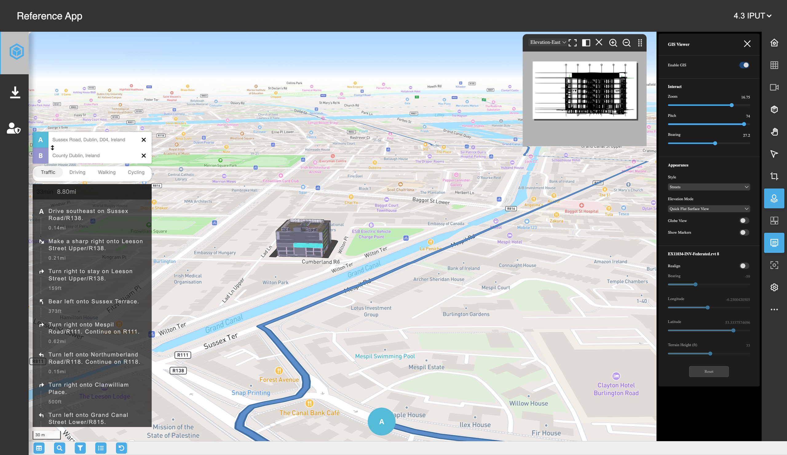
Figure: Reference app with GIS enabled
Mapbox#
The IafViewer uses Mapbox to view building models on a GIS map. Mapbox uses temporary tokens to access map information. For more information on using Mapbox, refer to the page on Mapbox tokens.
Loading and aligning a BIM project#
When a BIM project is first loaded, it is not geolocated correctly and defaults to a pre-set longitude and latitude within a country.
To position the model accurately in a real-world setting, you need to do the following:
- Set longitude and latitude co-ordinates: Defines the precise geolocation of the building.
- Set the bearing and tilt: Adjusts the orientation and angle of the model.
- Specify the elevation (in feet): Determines how much of the building is positioned above or below the terrain ground level.
- Carry out individual alignment: Each building requires individual alignment for accurate placement.
Launching the GIS feature#
To launch the GIS feature, do the following:
Click the GIS Launcher icon in the toolbar on the right of the Model Navigator page.
The GIS configuration pane will appear. Click the Enable GIS switch button to activate the GIS features.
GIS Enabled IafViewer - Interaction pane#
The GIS Interation Pane allows you to dynamically adjust the camera view in the GIS environment.
It consists of three primary controls:
- Zoom
- Pitch
- Bearing
The three actions (Zoom, Pitch, and Bearing) affect both the 3D model and the underlying GIS map. Adjustments made via the Interaction pane are synchronized so that both the model and the map reflect the same spatial perspective. This ensures consistent and accurate navigation throughout the application.
Figure: GIS Interaction pane
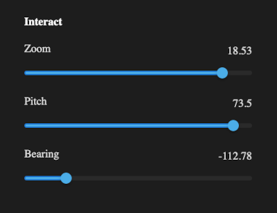
GIS Interaction pane primary controls#
Zoom control#
The Zoom control determines how close or how far the camera is from the model or map surface.
Note the following guidelines:
- Range: Typically 0 (furthest) to around 22 (closest). Exact limits may vary by map style.
- Lower values: Offers a broad, distant view of the map.
- Higher values: Zooms in closely to reveal finer details of the building or site.
Pitch control#
The Pitch control adjusts the tilt of the camera relative to the map's surface.
Note the following guidelines:
- Range: Typically, 0° (looking straight down) to around 85° (near horizontal). Effect:
- Lower values: Lower Values (0°–30°): More top-down, “bird’s-eye” perspective.
- Higher values: Higher Values (30°+): More oblique angle, enabling a horizon view of the building in the GIS context.
Bearing control#
The Bearing control rotates the camera around the vertical axis, altering the compass direction in which you are facing.
Note the following guidelines:
- Range: Typically -179° to 180°
- Positive or negative values: Changes the orientation of the map, letting you face north, east, south, or west (and anywhere in between).
GIS Enabled IafViewer - Appearance/Display settings pane#
The Appearance/Display settings pane provides controls for customizing the visual presentation of the map and BIM models.
Appearance settings#
Figure: Appearance settings pane
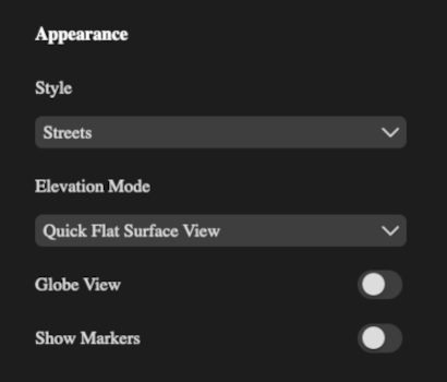
The Appearance settings pane provides controls for customizing the visual presentation of the map and BIM models.
In this pane, you can change the following settings:
- Style
- Elevation Mode
- Globe View
- Show Markers
Style setting#
The purpose of the Style setting is allow the selection of different maps styles which define the look and feel of the map's terrain and road networks.
For the Style: setting, common values include
- Streets
- Satellite
- Outdoors
- Light
- Dark
Note that changing the Style value immediately updates the map background, roads, and terrain presentation. BIM models remain in place, but their surrounding environment adopts the chosen style.
Elevation mode setting#
The purpose of the Elevation Mode setting is to determine how above-ground and below-ground elements are rendered.
Changes to the elevation mode will alter how much of the building is visible above or below the map's surface. It is useful for analyzing underground utilities or verifying building foundation depths.
Common values for the Elevation Mode include:
- None - All elements are rendered the same regardless of level.
- Quick Flat Surface View - Displays the terrain as a flat surface, making underground elements appear clearly beneath the building.
- Quick Flat Subsurface View - Displays the terrain as a flat surface, making overground elements appear clearly above the building.
Globe View setting#
The Globe View setting button toggles between a building view (flat view) and a global (3D) view of the Earth.
When set to ON, the Globe View helps visualize large-scale geography and indicates the building project's position relatve to entire countries or continents. When not turned on, the flat view is ideal for detailed, close-up inspections of the building site.
To summarize, the Globe View setting behaves as follows:
- ON: Displays the map as a globe, allowing you to see the project's location on a 3D model of the Earth.
- OFF: Displays a closer view of a building site, with the default view being the primary building.
Show Markers setting#
The Show Markers setting button toggles the visibility of markers on the map. These markers can indicate things such as buildings belonging to the active project, the reference point, or the centre of orbit.
Markers can help orient buildings or label specific buildings in relation to a reference point. However, turning off markers can reduce visual clutter while focusing on building geometry or terrain details.
To summarize, the Show Markers setting behaves as follows:
- ON: Displays all configured markers on the map.
- OFF: Hides markers, providing a cleaner view of the terrain and building models.
Geo Referencing/Alignment controls#
Every building in the project can be realigned independently using a range of controls for precise geopositioning.
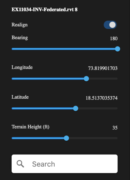
The main controls available are:
- Realign
- Bearing
- Longitude
- Latitude
- Terrain Height
- Search box
- Reset
Realign setting#
The Realign setting button toggles between enabling or disabling the building realignment mode.
It works as follows:
- ON: The pane's inputs become active, allowing you to modify the building's geospatial settings.
- OFF: The building remains in its current state, and any unsaved changes are discarded.
Bearing setting#
The Bearing setting specifies the rotation of the building around the vertical axis on Earth's surface. It has the effect of adjusting the building's orientation (north-south-east-west) relative to the map.
The range of this setting is typically between -179° to 180°.
Longitude setting#
The Longitude setting defines the east-west position of the building. Changing this value will move the building horizontally. The value is formatted in decimal degrees, for example, -6.2504020505.
A positive change in this value will move the building to the east, whereas a negative change will move the building to the west.
Latitude setting#
The Latitude setting defines the north-south position of the building. Changing this value will move the building veritically (north/south). The value is formatted in decimal degrees, for example, 53.3337574696.
A positive change in this value will move the building to the north, whereas a negative change will move the building to the south.
Terrain Height (ft) setting#
The Terrain Height (ft) setting specifies how much of the building's structure is below ground level. This setting is measured in Feet (ft).
The effect of higher values in this setting, will mean that a larger portion of the building is placed below the terrain. Lower values mean that most of the building is above ground.
Search box#
The Search box allows you to enter an address or location and the map will quickly jump directly to that specific area.
The Search box will be active, once you activate the Realignment Mode. When you enter an address, the map view will be updated, assisting in locating and relaligning the building relative to its actual geographic position.
Reset#
The Reset option reverts the building to its previous geospatial setings, before entering realignment mode. A reset will discard any changes made to the bearing, longtitude, latitude, and terrain height settings and restore the building settings to the last saved alignment state.