Export settings
Overview#
The Navisworks IPA plug-in exports model metadata as a SGPK file; plug-in users can use the Export Settings dialog to configure export functions on following items:
- Which element properties to export
- Which Plant Design Management Systen (PDMS) Type codes are considered for model elements or containers, if you are exporting a Navisworks model containing PDMS source model or
.rvmfile
Configuring export settings#
Pre-requisite: Before using the Export Settings dialog, check your model and appraise which element properties to export. For each property, you need to know its property-group name and property name. For a PDMS source model, appraise the PDMS Type Codes for model elements or containers.
To open the IPA - Export Settings dialog, click the Export Settings icon.
On the Common Properties tab, if the property group you want to configure is not in the table, click ADD to add it.
For your property group, specify which properties to include and exclude.
Note:
- Specified properties that do not exist are ignored
- If you leave the Included Properties column empty, all the property group's properties are exported.
On the Special Properties tab, if the model source type you want to configure is not in the source type list, click Add to add it. Use the CAD file's extention, for example use
.rvtfor Revit model source type.For your source type, specify which properties to include and exclude.
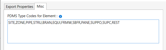
If you have a PDMS model, to configure which PDMS Type Codes are considered for model elements or containers, go to the Misc tab. If you want to add more PDMS Type codes than the default value, add the codes with comma separation.
Note: Settings are saved in the file
ExportSettings.configin plug-in folder.
Figure: Export settings dialog
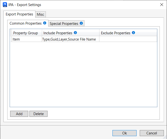
Figure: PDMS type codes settings
Export properties#
Common properties#
For all nodes in the Navisworks model tree, there are common, built-in Navisworks properties, which are not imported from source model. These properties are under property groups like Item, TimeLiner, and Material.
Special properties#
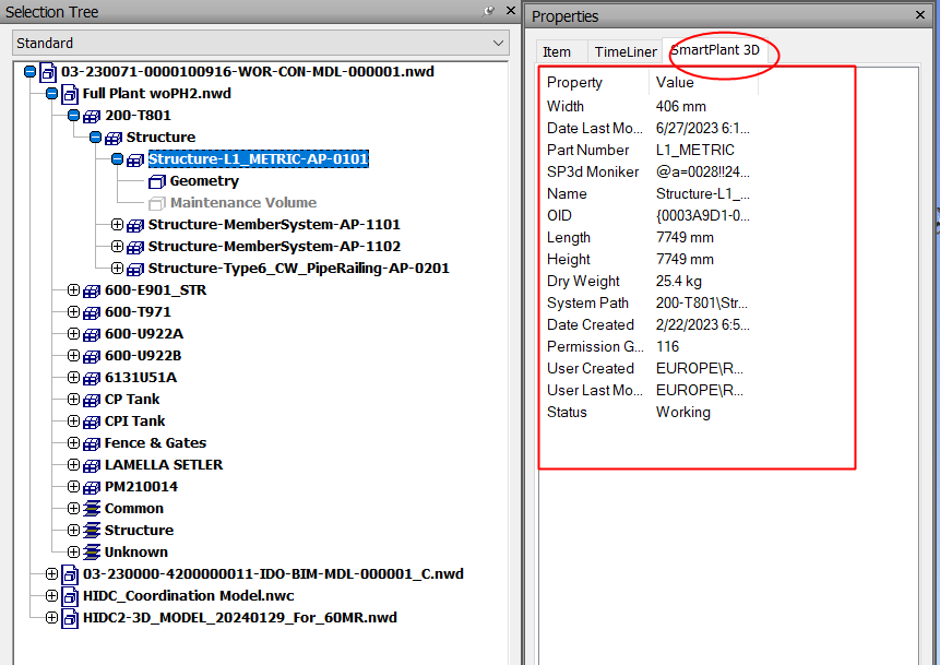
Different types of source CAD models have their own special properties. For example, for a SmartPlant 3D source model, the special properties are under the SmartPlant 3D property group.
Figure: SmartPlant 3D special properties
PDMS Type codes in PDMS model#
Plant Design Management Systen (PDMS) models imported into Navisworks don't have GUIDs for model elements. In such cases, use the PDMS/Type property value to determine if a node in the model tree represents a physical model element. This enables it to be selected and highlighted in the IafViewer.
Note: In PDMS models,
PDMS/TYPEis a metadata attribute assigned to each 3D object such as a pipe, structure, or piece of equipment, to classify its role in the plant design.
Refer to PDMS/TYPE examples in the following table:
| TYPE | Description | Role |
|---|---|---|
SITE | SITE represents the highest-level organizational element within the model's hierarchy. It is used to define the overall project site and serves as the top-level container for all other elements and structures within the design. | Container |
ZONE | ZONE is a significant organizational element that is typically one level below the SITE in the hierarchy. A ZONE represents a specific area or section within the overall project site. It is used to group related elements and structures that belong to a particular functional or geographical area. | Container |
PIPE | PIPE indicates a group of branches | Container |
BRAN | BRAN represents a branch in the piping system. A branch is a section of piping that extends from a main pipe to distribute the flow of fluids to different areas or equipment. It typically includes various components such as pipes, elbows, tees, and valves. | Element |
EQUI | EQUI is used to represent various types of equipment and machinery within the design. These can include pumps, compressors, heat exchangers, vessels, tanks, and other mechanical or electrical equipment essential to the plant or facility. | Element |
FRMW | Indicates Framework, which in a PDMS model often serves as a container or organizational structure for other elements like beams, columns, and sub-frames. It is a higher-level grouping element that helps structure the overall design. | Container |
SUBE | Indicates sub-element, part of equipment. | Sub-component |
CYLI | Indicates cylinder. | Geometry |
CONE | Represents conical shapes, often used in equipment or structural designs. | Geometry |
SBFR | Indicates sub-frame, used for organizing structural components within a framework. | Container |
GENSEC | Indicates general section. Represents structural elements with a defined cross-section. | Sub-component |
PANE | Indicates panel. Often used for flat structural elements such as walls or partitions. | No component |
BRCE | Indicates brace. Used for diagonal supports in structural frameworks. | Sub-component |
TUBE | Indicates tube. Represents hollow, cyclinderical components. | Sub-component |
PLTE | Indicates plate. Used for flat, solid components in structures. | Sub-component |
ELBO | Indicates elbow. Used in piping systems for directional changes. | Sub-component |
FLAN | Indicates flange. A sub-component in piping, used for connecting pipes or equipment. | Sub-component |
ATTA | Indicates attachment. Used to represent various types of attachments or connection points within the design. | Sub-component |